


Electrical troubleshooting can feel overwhelming, especially when you’re trying to determine whether power is flowing through a switch. A voltmeter becomes your most reliable diagnostic tool in these situations, helping you identify electrical issues quickly and safely.
Understanding how to measure power in a switch using a voltmeter properly is an essential skill for electricians, maintenance technicians, and DIY enthusiasts. This guide will walk you through the entire process, from selecting the right equipment to interpreting your readings accurately.
Whether you’re diagnosing a faulty light switch, testing industrial equipment, or performing routine electrical maintenance, mastering voltmeter techniques will save you time and prevent costly mistakes.
Understanding Voltmeter Basics
A voltmeter measures the electrical potential difference between two points in a circuit. When testing switches, you’re essentially checking whether voltage is present on both sides of the switch and whether it flows through when the switch is activated.
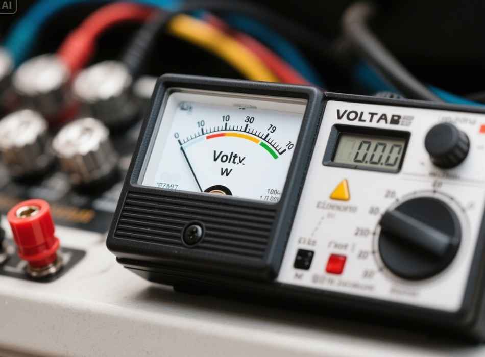
Digital multimeters (DMMs) are the most common type of voltmeter used today. They offer several advantages over analog meters, including higher accuracy, better resolution, and additional measurement functions. Most modern DMMs can measure both AC and DC voltage, making them versatile tools for various electrical applications.
Before using any voltmeter, please familiarize yourself with its settings and limitations. Check the maximum voltage rating to ensure it can handle the electrical system you’re testing. Most household electrical systems operate at 120V or 240V AC, while industrial systems may use higher voltages that require specialized equipment.
Safety Precautions and Preparations

Electrical safety should always be your top priority when working with voltmeters and switches. Even seemingly simple measurements can pose serious risks if proper precautions aren’t followed.
Always assume that circuits are live until proven otherwise with your voltmeter. Turn off power at the circuit breaker before beginning any work, but remember that testing often requires the circuit to be energized. Use appropriate personal protective equipment, including safety glasses and insulated gloves rated for the voltage level you’re working with.
Inspect your voltmeter and test leads before each use. Look for cracked insulation, damaged probes, or loose connections that could create safety hazards. Test your meter on a known voltage source to verify it’s working correctly before proceeding with your measurements.
Ensure you have adequate lighting and a stable work surface. Keep one hand behind your back when possible to reduce the risk of creating a path for electrical current through your body.
Step-by-Step Measurement Process

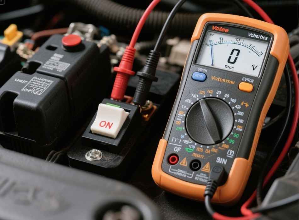
Start by setting your voltmeter to the appropriate voltage range. For AC measurements, select the AC voltage function and choose a range higher than the expected voltage. If you’re unsure about the voltage level, start with the highest range and work your way down for more precise readings.
Position your test leads carefully. The black lead typically connects to the standard (COM) terminal, while the red lead connects to the voltage (V) terminal. Ensure both leads are firmly seated in their respective jacks.
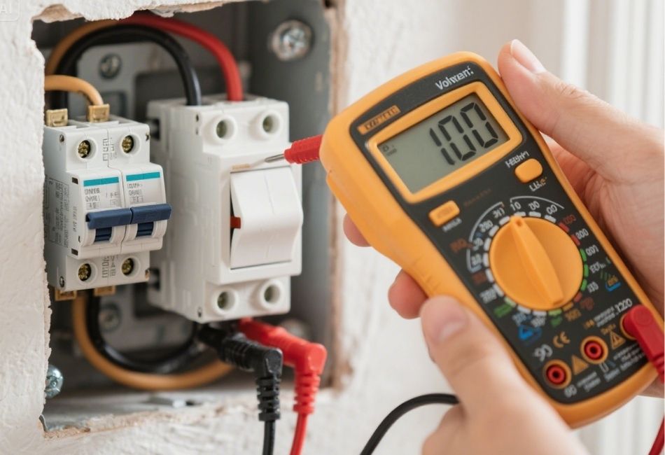
To test for incoming power, place one probe on the neutral wire or ground and the other on the hot wire entering the switch. A reading close to your system’s rated voltage indicates power is present. For a 120V system, you should see approximately 120V on your display.
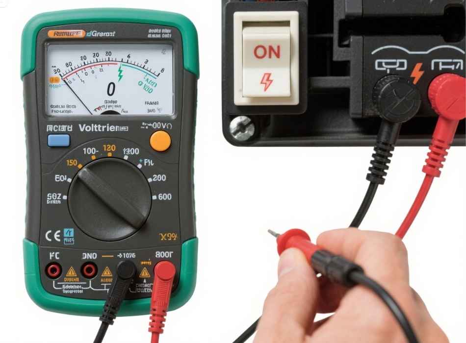
Next, test the switch’s output by keeping one probe on neutral or ground and moving the other to the switch’s output terminal. With the switch in the OFF position, you should read zero volts. When you flip the switch to ON, the reading should match your input voltage, confirming the switch is functioning correctly.
Interpreting Voltmeter Readings
Understanding what your voltmeter readings mean is crucial for accurate diagnosis. A reading of zero volts across a closed switch indicates the switch is working correctly, as there should be no voltage drop across a properly functioning switch in the ON position.
If you measure significant voltage across a closed switch, this suggests the switch contacts are dirty, corroded, or worn out. Even a reading of just a few volts can indicate problems that will worsen over time.
Inconsistent readings may point to loose connections or intermittent contact issues. If voltage readings fluctuate when you wiggle wires or manipulate the switch, investigate all connection points for tightness and corrosion.
Remember that your voltmeter has finite input impedance, which can affect readings in high-impedance circuits. This is rarely an issue with standard switch testing, but it’s worth understanding for more complex electrical diagnostics.
Common Switch Testing Scenarios
Single-pole switches are the most straightforward to test. These switches simply make or break one circuit path. Test for voltage on both the input and output terminals, and verify that the switch can control the flow of power to your load.
Three-way switches require a more systematic approach since they have three terminals and work in pairs—test between the common terminal and each traveler terminal with the switch in both positions. The voltage should alternate between the two traveler wires as you flip the switch.
Four-way switches, used in circuits controlled from three or more locations, have four terminals and require testing between all possible combinations. Document your findings to track which terminals are connected in each switch position.
When testing switches in motor control circuits or other industrial applications, be aware that you may encounter higher voltages and more complex switching arrangements. Always consult electrical diagrams and follow lockout/tagout procedures.
Troubleshooting Common Issues
No voltage reading at the switch input typically indicates a problem upstream in the circuit. Check the circuit breaker, fuses, and wiring connections leading to the switch. Use your voltmeter to trace the circuit back to the source.
Partial voltage readings might suggest loose connections, corroded terminals, or parallel paths in the circuit. Clean all connection points and ensure wire nuts or terminal screws are correctly tightened.
If you measure voltage at the switch output but the connected device doesn’t operate, the problem likely lies in the load circuit rather than the switch itself. Test continuity through the device or check for proper grounding.
Erratic readings often point to mechanical issues within the switch mechanism. Internal contacts may be worn, burned, or misaligned. In most cases, replacing the switch is more cost-effective than attempting repairs.
Making Sense of Your Measurements
Proper voltmeter technique transforms electrical troubleshooting from guesswork into systematic diagnosis. By following these procedures, you can quickly identify whether switches are functioning correctly and pinpoint problems in electrical circuits.
Remember that voltmeter measurements are just one part of comprehensive electrical testing. Combine voltage readings with continuity tests, current measurements, and visual inspections for complete circuit analysis.
Practice these techniques on known-good circuits before tackling problematic ones. The more familiar you become with regular readings and switch behavior, the more effectively you’ll diagnose unusual conditions.